Documentation
Robert Laszlo, Martin Koleda
·NXTRX4 Cormorant
Ham Radio User Guide
Telemetry Data
1. Introduction
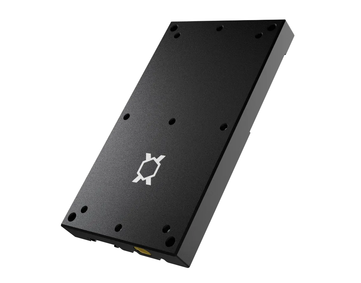
Needronix developed a new miniature transceiver for cubesat/smallsat missions [*4]. It allows the use of ham radio (radio amateur) frequencies in VHF 145 MHz and UHF 440 MHz bands. Therefore benefits for radio amateurs were accentuated so that these could participate. The radio is versatile and platform-independent, it is deployable using a standard PC104 Bus, as well as other buses - e.g. Backplain (CSID - Prof. Dr. Klaus Schilling, UNISEC Europe [*5]). The mainboard (as seen in Figure 1 - VHF and UHF transceiver) serves only as an interconnection to different buses thus other satellite on-board systems.
Cormorant transceiver utilizes Cubesat Space Protocol [*2] to forward messages to and to communicate with other subsystems, as well as for its own management and configuration. CSP Protocol description is not within a scope of this document. See Wikipedia for basic information on CSP [*1].
Purpose of this document is to provide a brief guide to radio amateurs on satellite identification, operation parameters monitoring and use of digipeater.

2. Transmission description
The highest priority of the Cormorant Transceiver is the receive mode. It is necessary for the satellite mission that the radio is able to receive under any circumstances. This prevailing mode is only interrupted by a transmit request, which can happen in user-configurable regular intervals, bi-directional communication with the Ground Segment or on-demand from external subsystems within the satellite.
There are three types of transmit requests:
- Internal - Cormorant telemetry, command and data
- Internal - Digipeater
- External - External telemetry, command and data
The type of request is traceable inside of the message body. More detailed description in chapter 4.

Packets (messages) are encapsulated into higher level AX.25[*3] protocol for ham radio enthusiasts or into CSP Protocol for the service purposes and maintenance. There is a simple rule: if the packet is not AX.25, it is CSP then.
- Default AX.25 telemetric packet interval: 30 s.
- Default morse interval: 90 s.
- Any of these timing settings can be changed in-flight by the satellite operators without notice.
- Digipeater is always on. It might be turned off exceptionally for the sake of a demanding experiment.
- If your receiver is not set up to display strictly AX.25 messages only, you will see the CSP packets as well.
- Note that according to Figure 2, a CSP or a telemetry packet can show up between your AX.25 digipeater packet and a digipeater response to you.
Recommended TNC modem setup:
- PACLEN 255
- TXDELAY 15
- MYCALL [Your call sign]
- NPROTO CQ (or callsign)
3. Satellite radio link setup
- Modulation: GFSK,
- Encoding: G3RUH compatible, 9600 bps, 8bit
- Output power: max 1W (30dBm)
- Onboard antenna: Dipole
- Antenna polarisation: Linear
4. AX.25 Basic Cormorant Telemetry
System message is a CSV formatted text with a comma as a separator followed by a part identifier (U, R, V, etc.). Messages can be stored, imported and comfortably processed in any spreadsheet.
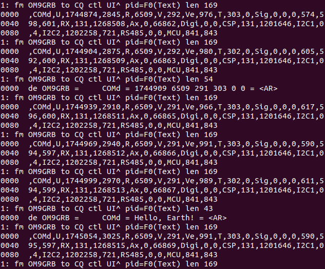
System Status Message Example (this is a real packet captured via radio transmission):
,COMd,U,1696079,1825,R,6496,V,282,Ve,937,T,301,0,Sig,0,0,0,616,607,612,RX,125,1244909,Ax,0,65294,Digi,0,0,CSP,125,1179615,I2C1,0,4,I2C2,1180233,721,RS485,0,0,MCU,835,837
All numbers represented here are decimal. No other format (oct, hex) is used. COMd - fixed length 4 bytes consisting of 3 bytes device name acronym followed by one additional byte - e.g. OBC1, OBC2, COMd (‘d’ as downlink), COMu (‘u’ as uplink), GPS1 etc.

Data packet doesn’t have a fixed structure - the packet is divided by the comma separator to 15 parts - see table below.
Message items detailed description:
| Part | Example | Name | Description |
|---|---|---|---|
| 0 | ,COMd, | Subsystem identifier | 4 bytes (internal NXTRX packet as COMx) - Mission specific. |
| 1 (U) | U,1696079,1825, | Uptime | <total_uptime[s]>, <uptime_since_last_reset[s]> |
| 2 (R) | R,6496, | Reset counter | This includes any reset source - Brown-out, Watchdog, SW etc. |
| 3 (V) | V,282, | MCU V | Microcontroller supply voltage [x10mV] |
| 4 (Ve) | Ve,937, | AUX V | Auxiliary voltage measurement of an external voltage from other devices in the satellite. Raw data: 12bit range vs 2.5V Reference voltage. Note that in order to be able to measure any on-board voltage, this voltage is being divided in a resistor voltage divider. Look for mission specific details in order to get the proper division ratio. Example: GRBAlpha Vbat [mV] = Ve * 3,3713 2S1P - 2x Li-Ion 18650 Critical= 6500 mV Safe = 6700 mV Normal = 7000 mV Max = 8300 mV |
| 5 (T) | T,301,0, | Temperature | <CPU_core_temperature[K]>, <power_amplifier_NTC_raw_data> See 9. Apendix II |
| 6 (Sig) | Sig,0,0,0,616,611,614, | Radio signal | <sigRxImmediate>, <sigiRxAvg>, <sigRxMax>, <sigBackgroundImmediate>, <sigBackgroundAvg>, <sigBackgroundMax> |
| 7 (RX) | RX,125,1244909, | RF side packet counter | <packets_received>, <packets_transmitted> Transceiver packet counters - CSP and AX.25 system messages, digipeater. Note that ‘RX’ = ‘AX.25’ + ‘CSP’. |
| 8 (Ax) | Ax,0,65294, | AX.25 packet counters: | <packets_received>, <packets_transmitted> |
| 9 (Digi) | Digi,0,0, | Digipeater counters: | <digipeaterRxCount>, <digipeaterTxCount> |
| 10 (CSP) | CSP,125,1179615, | RF side CSP packet counters | <packets_received>, <packets_transmitted> |
| 11 (I2C1) | I2C1,0,4, | I2C1 packet counters | <packets_received>, <packets_transmitted> |
| 12 (I2C2) | I2C2,1180233,721, | I2C2 packet counters | <packets_received>, <packets_transmitted> |
| 13 (RS485) | RS485,0,0, | RS485 packet counters | <packets_received>, <packets_transmitted> |
| 14 (MCU) | MCU,835,837 | CSP interface packet counters | <packets_received>, <packets_transmitted> |
Example from TNC:

5. Subsystem AX.25 telemetry
A subsystem might request its packet to be sent while only the obligatory parameter is a subsystem identifier (e.g. OBC2, PAY1 etc.). Content of these messages is closely subsystem related, for more info search for the specific mission details.
| Part | Example | Name | Description |
|---|---|---|---|
| 0 | OBC1, | Origin | 4 bytes - obligatory |
| 1 | XXXXX…..XXXXXX | User msg | max 200 bytes of subsystem messages (binary, base64, text) - follow mission details |
6. Morse telemetry
Every basic Morse system status message is preceded by its digital copy transmitted in AX.25 protocol:
de MYCALL = AAAX = num1 num2 num3 num4 num5 num6 = <AR>
MYCALL:
- is a callsign (OM9GRB for example)
AAAX:
- is an identifier of a device/subsystem sending the data
num1 to num6:
- in AX.25 message: uint32_t number in decimal format (i.e. 0 to 4,294,967,295) in Morse message: decimal format of 6 uint32_t numbers (i.e. 0 to 4,294,967,295), but in order to save some transmitting time for the digits, every digit is translated into a less time consuming Morse code (see Appendix I. table - Morse effective digit conversion )
Morse WPS (speed): 20 - can be changed in flight by the satellite operators without notice.
Example of AX.25 message (copy of morse message):

Example of the same message in Morse:
DE OM9GRB = COMD = AD446T6 NET6 U6A VTV T T = <AR>
If the device/subsystem identifier is “COMd” or “COMu”, it is a message originating in the Cormorant radio and num1 to num6 represent:
| num1 | totalUptime [s] |
| num2 | totalResetCount |
| num3 | cpuVoltage [x10mV] |
| num4 | cpuTemp[K] |
| num5 | 0 - Reserved |
| num6 | 0 - Reserved |
For other subsystems identifiers search for the specific mission details.
7. Digipeater mode
A valid Ax25 packet is retransmitted by the digipeater while complying to the Ax.25 digipeater standard of adding the satellite callsign into the Ax.25 header. A delay between receiving and retransmitting of the message is configured to 1300ms and can be reconfigured during flight by the satellite operator without notice. SSID of digipeater is 7.

Example of QSO via digipeater

Appendix I. - morse number conversion table
Morse conversion table - the purpose of this conversion is to minimize the dash ‘-’ count in the transmitted number in order to minimize the transmission time.
Try our online morse convertor for Cormorant.
| Received character | Dash-dot | Original number |
|---|---|---|
| T | - | 0 |
| A | .- | 1 |
| U | ..- | 2 |
| V | ...- | 3 |
| 4 | ....- | 4 |
| E | . | 5 |
| N | -. | 6 |
| D | -.. | 7 |
| B | -... | 8 |
| 6 | -.... | 9 |
9. Appendix II. - NTC temperature conversion table
Table below provides conversion from NTC ADC reading to temperature [°C]
| ADC Value | Temp [°C] | ADC value | Temp [°C] |
|---|---|---|---|
| 4054 | -55 | 1084 | 50 |
| 4036 | -50 | 941 | 55 |
| 4011 | -45 | 815 | 60 |
| 3978 | -40 | 705 | 65 |
| 3934 | -35 | 609 | 70 |
| 3877 | -30 | 527 | 75 |
| 3804 | -25 | 456 | 80 |
| 3713 | -20 | 395 | 85 |
| 3602 | -15 | 342 | 90 |
| 3469 | -10 | 297 | 95 |
| 3313 | -5 | 259 | 100 |
| 3136 | 0 | 226 | 105 |
| 2939 | 5 | 197 | 110 |
| 2726 | 10 | 173 | 115 |
| 2503 | 15 | 152 | 120 |
| 2275 | 20 | 134 | 125 |
| 2048 | 25 | 118 | 130 |
| 1827 | 30 | 104 | 135 |
| 1618 | 35 | 93 | 140 |
| 1423 | 40 | 82 | 145 |
| 1245 | 45 | 73 | 150 |
If you want to use information from this user guide, provide link to this page.
[1] Cubesat Space Protocol - https://en.wikipedia.org/wiki/Cubesat_Space_Protocol
[2] CSP developed by GOMSpace https://gomspace.com/home.aspx
[3] AX.25, G3RUH http://www.tapr.org/pdf/AX25.2.2.pdf https://www.amsat.org/amsat/articles/g3ruh/109.html
[4] Cubesat https://www.cubesat.org/cubesatinfo
[5] CSID - http://unisec-europe.eu/wordpress/wp-content/uploads/CubeSat-Subsystem-Interface-Standard-V2.0.pdf